RF Hacking My Wireless Lights
December 11, 2021
RF hacking to reverse engineer the wireless remote for my wireless cabinet lights.
I picked up a pretty cheap set of under cabinet lights for my workbench awhile ago on Amazon. The lights are great and all but they are solely controlled by the remote that comes with them. No manual button next to the receiver. The remote itself is fairly bulky and always just sits on top of the workbench. Ideally I would want to be able to This left me with a few options:
- Add a relay between the lights and their power source.
- Circuit bend the remote to make it a more under desk mountable form factor.
- Reverse engineer the remote’s signal to make own remote.
Naturally I went with the harder approach: reverse engineering the remote’s signal.
Investigating the remote
First things first we need to figure out how the remote communicates with the receiver that is directly attached to the lights. Looking at the remote we can see that there is not visible LEDs that could be used to send IR signals to the receiver.
Running around our house I was surprised by the range and how well the remote was able to communicate with the receiver, tipping off that it was probably some transmitting at a lower frequency.
Using SDRs + URH = <3
Leveraging my hunch that I was working in the lower frequency range and that I couldn’t find any FCC certification information on the remote or receiver I figured it was operating in the LPD433. This is also the band in which some garage or gate openers operate in.
With that I hooked my RTL-SDR to my workstation and installed Universal Radio Hacker (URH). URH is a great suite for wireless protocol analysis with built in support for my RTL-SDR.
Opened up the spectrum analyzer and got my remote real close to my SDR and start clicking all of the buttons. Bingo! I was able to see a spike at 433.9Mhz in the spectrum analyzer.
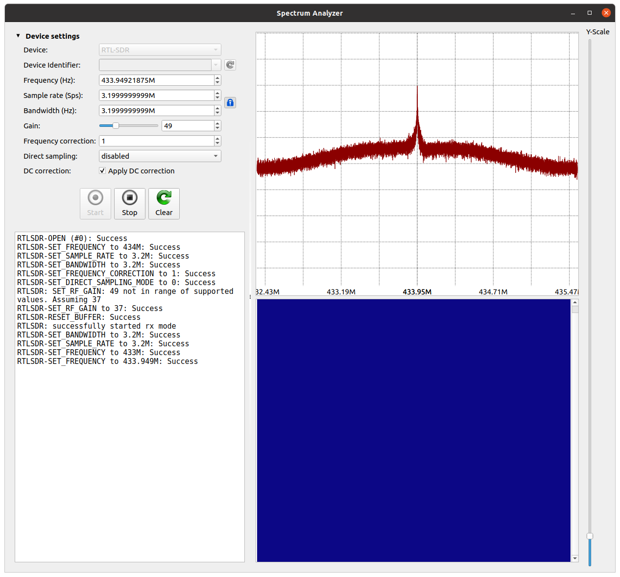
With that, I locked in on that frequency and started recording all of the button presses from the remote. Now onto seeing if we can tease out the control signal itself.
When you first open up a recording, URH will default to trying to interpret the signal using FSK modulation. Zooming in, I was able to see the distinct button presses in my recording, but was not really able to see anything sensible signal in it.
Changing the Modulation to ASK and setting the Signal View to Demodulated I started to see clear bits being set high to low.
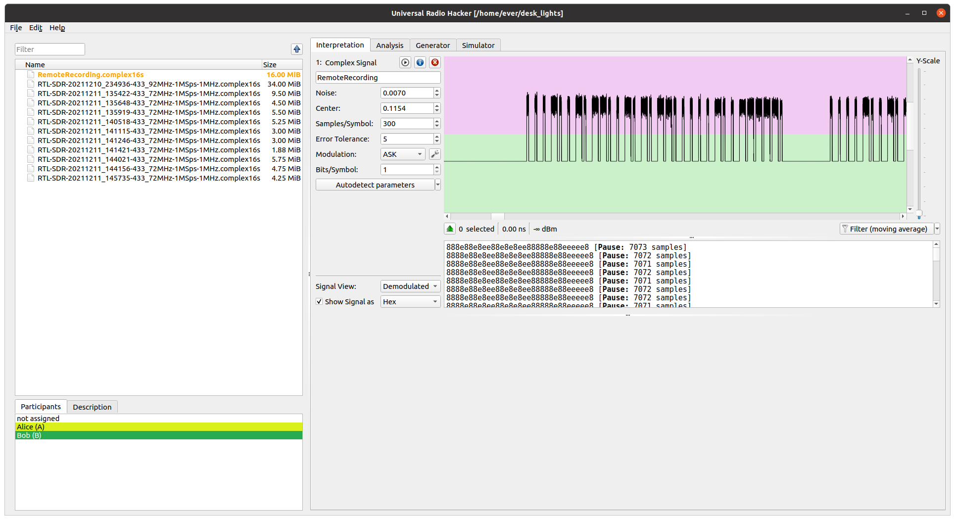
However trying to see the signal as a hex encoded string was producing some pretty weird results.
All was not lost however, from eyeing the signal I found that:
- The signally clearly repeated itself as you held the button down.
- There wasn’t any additional encryption or state being transmitted since the signal was just repeating itself over and over again.
At this point it was just a matter of dialing in the Samples/Symbol so that I got a nice repeating hex string for each pulse. I eventually found that 500 Samples/Symbol seemed to do the trick:
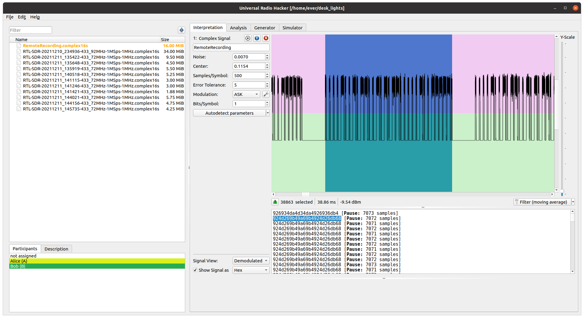
Sweet! Now I have a signal that I need to transmit for an “ON” and “OFF” signals: 924d269b49a69b4924d26db68 and 924d269b49a6d349249a6db68.
Breaking this down a little further I can also extract the bit rate of the signal from this recording seeing that the highlighted region occurred over 38.86 ms for 13 bytes of data. This puts the bit rate right at around 2.7 kbps (note: bits-per-second not bytes-per-second).
Building the Transmitter
Hardware
For the transmitter I used a CC1101 with an Arduino Nano. The CC1101 is an inexpensive sub-1 GHz transceiver. I picked up a pair of them on Amazon for ~ $10 USD. An important note: the CC1101 technically operates at 3.3V and not 5V. The Nano on the other hand is a 5V board. So I added a few logic level bidrectional converters to convert the 5V signals to 3.3V signals and vice versa. Some anecdotal discussions on a few forums mention that you might be able to get away with operating the CC1101 at 5V but I don’t recommend it and don’t want to be responsible for ruined hardware.
Now armed with our Frequency (433.9MHz), Modulation mode (ASK), Bitrate (2.7 kbps), and Signals, lets make the transmitter!
I ended up wiring my breadboard up using the schematic below:
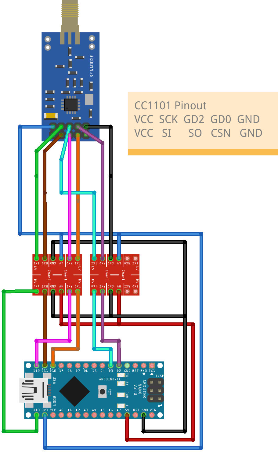
Since the schematic above might be hard to read, here’s a table of the CC1101 to Nano connections through the Logic Level Converter:
| CC1101 |
Nano |
| GD0 |
D2 |
| GD2 |
D3 |
| CSN |
D10 |
| SI |
D11 |
| SO |
D12 |
| SCK |
D13 |
For those who don’t know how to use a Logic Level Converter, the pins are labeled HV on one side and LV on the other. HV corresponds to the 5V side of inputs/outputs and LV the 3.3V side.
Software
For driving the CC1101 I used the https://github.com/jgromes/RadioLib library that can be downloaded in the Arduino IDE by jgromes. Their library has a nice set of examples that go over how to Transmit and Receive using the CC1101 in an Arduino environment.
Below is the final code that I have running on the micro controller:
// Using an Arduino Every Nano
#define GD0 2
#define CSN 10
#define SI 11
#define S0 12
#define SCK 13
#define GD2 3

// RadioLib helpful defines
#define ERR_NONE RADIOLIB_ERR_NONE
#define MAX_PAYLOAD 63

// Optional LED for on/off state of tx
#define LED_PIN 4

#include <RadioLib.h>

CC1101 radio = new Module(CSN, GD0, RADIOLIB_NC, GD2);

byte on_payload[] = {
  0x92, 0x4d, 0x26, 0x9b, 0x49, 0xa6, 0x9b, 0x49, 0x24, 0xd2, 0x6d, 0xb6, 0x80
};
int on_size = 13;
byte off_payload[] = {
  0x92, 0x4d, 0x26, 0x9b, 0x49, 0xa6, 0xd3, 0x49, 0x24, 0x9a, 0x6d, 0xb6, 0x80
};
int off_size = 13;

void setup() {
  pinMode(LED_PIN, OUTPUT);

  Serial.begin(9600);

  Serial.print(F("[CC1101] Initializing ... "));
  int state = radio.begin(
    /* freq */ 434.0,
    /* bit rate*/ 2.7,
    /* feqDev */ 5.0,
    /* rx bandwidth */ 250.0, // not needed for TX only
    /* txPower */ 7,
    /* preambleLen */ 16);

   Serial.print(F("[CC1101] Setting Data shaping to NONEE ... "));
   state = radio.setDataShaping(RADIOLIB_SHAPING_NONE);
    if(state == ERR_NONE) {
     Serial.println(F("success!"));
   } else {
     Serial.print(F("failed, code "));
     Serial.println(state);
     while(true);
   }

   Serial.print(F("[CC1101] Setting encoding to NRZ ... "));
   state = radio.setEncoding(RADIOLIB_ENCODING_NRZ);
   if(state == ERR_NONE) {
     Serial.println(F("success!"));
   } else {
    Serial.print(F("failed, code "));
     Serial.println(state);
     while(true);
   }

  Serial.print(F("[CC101] Setting transmit mode to ASK/OOK ..."));
  state = radio.setOOK(true);
  if(state == ERR_NONE) {
    Serial.println(F("success!"));
  } else {
    Serial.print(F("failed, code "));
    Serial.println(state);
    while(true);
  }
}

void loop() {
  // Turn on the built-in led for visual feedback
  digitalWrite(LED_PIN, HIGH);
  // Transmit "on" signal
  transmitPayload(on_payload, on_size);
  // wait for 3 seconds before transmitting again
  delay(3000);

  digitalWrite(LED_PIN, LOW);
  // Transmit "off" signal
  transmitPayload(off_payload, off_size);
  delay(3000);
}

void transmitPayload(byte * payload, int payloadSize) {
  Serial.print(F("[CC1101] Transmitting packet ... "));
  int state = 0;

  // Check if we should send repeated signals
  if ((payloadSize + 2) < MAX_PAYLOAD / 2) {
    byte whiteSpace[2] = {0x00, 0x00};
    int offset = 0;
    int numRepeats=  MAX_PAYLOAD % (payloadSize + 2);
     byte transmitBuffer[(payloadSize + 2) * numRepeats];

    // Copy the payload into the buffer
    for ( int i =0 ; i < numRepeats; i ++ ) {
      memcpy(transmitBuffer + offset, whiteSpace, 2);
      offset = offset + 2;
      memcpy(transmitBuffer + offset, payload, payloadSize);
      offset = offset + payloadSize;
    }

    state = radio.transmit(transmitBuffer, offset);

  } else {
    state = radio.transmit(payload, payloadSize);
  }

  if (state == RADIOLIB_ERR_NONE) {
    // the packet was successfully transmitted
    Serial.println(F("success!"));

  } else if (state == RADIOLIB_ERR_PACKET_TOO_LONG) {
    // the supplied packet was longer than 64 bytes
    Serial.println(F("too long!"));

  } else {
    // some other error occurred
    Serial.print(F("failed, code "));
    Serial.println(state);

  }
}
The setup function has a few magic parameters that are needed to setup the CC1101 in the right mode to mimic the signal.
The transmitPayload function packs a few payloads repeated into a “single” packet that will be transmitted. This is because the CC1101 will by default add a preamble to clear the signal noise in the TX radio (called “whitening”… I think). I found it easier if I just packed more signal payloads after the preamble instead of trying to figure out how to disable it all together. In this case holding the button on the remote simply repeated the signal. This told me that the receiver probably continuously scans for relevant messages and re-transmitting the signal over and over again is totally fine for this application (at least the “on” or “off” states). Even if the first payload is ruined due to the preamble, subsequent payloads will be properly parsed.
One more thing, I added a diagnostic LED to pin 4 in the sketch but not the schematic. Simply wire a LED in series with a 470 ohm resistor to have it turn off and on with the most recent transmitted state.
Now to upload the code to the Arduino Nano, and … profit!
Next Steps
Now that I got the basic sketch working to turn my lights on/off, I need to build a case and a button to actually control my lights.
It would also be nice if I used a microcontroller with WiFi or Zigbee to bee able to configure and trigger it through my Home Assistant setup.